INTERODUCTION
The idea for this project is to remotely control an Arduino project using hand gestures. Let’s say we want to control the Arduino Robot Car that we mentioned above. So instead of the joystick we will use an MEMS module for the control.
Preface
A Robot is an electro-mechanical system that is operated by a computer program. Robots can be autonomous or semi-autonomous. An autonomous robot is not controlled by human and acts on its own decision by sensing its environment.
Majority of the industrial robots are autonomous as they are required to operate at high speed and with great accuracy. But some applications require semi-autonomous or human controlled robots
Some of the most commonly used control systems are voice recognition, tactile or touch controlled and motion controlled.
Some of the most commonly used control systems are voice recognition, tactile or touch controlled and motion controlled.
One of the frequently implemented motion controlled robot is a Hand Gesture Controlled Robot. In this project, a hand gesture controlled robot is developed using MPU6050, which is a 3-axis Accelerometer and 3-axis Gyroscope sensor and the controller part is Arduino Nano.
Instead of using a remote control with buttons or a joystick, the gestures of the hand are used to control the motion of the robot.
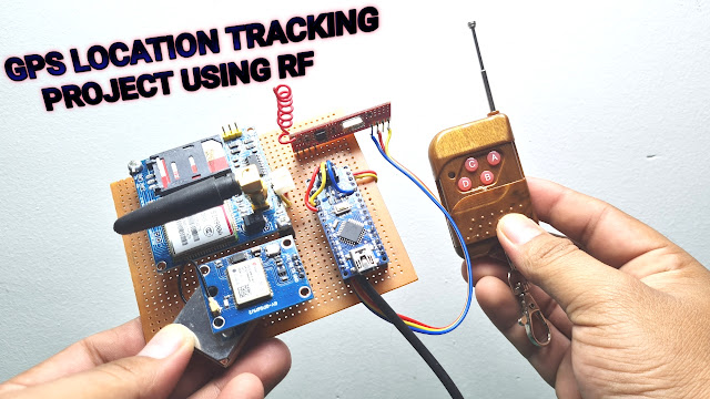
The project is based on wireless communication, where the data from the hand gestures is transmitted to the robot over RF link (RF Transmitter – Receiver pair).
The project is divided into transmitter and receiver section. The circuit diagram and components are explained separately for both transmitter and receiver sections.
Principle of Hand Gesture Controlled Robot
In order to understand the principle of operation of Hand Gesture Controlled Robot, let us divide the project into three parts.
The first part is getting data from the MPU6050 Accelerometer Gyro Sensor by the Arduino. The Arduino continuously acquires data from the MPU6050 and based on the predefined parameters, it sends a data to the RF Transmitter.
The second part of the project is the Wireless Communication between the RF Transmitter and RF Receiver. The RF Transmitter, upon receiving data from Arduino (through the Encoder IC), transmits it through the RF Communication to the RF Receiver.
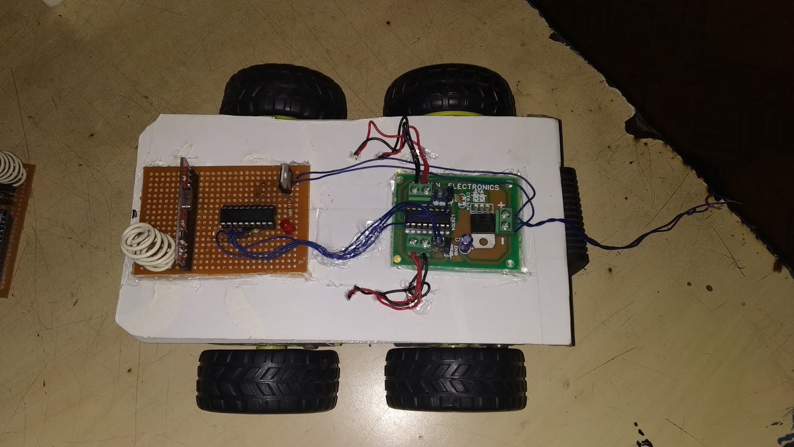
Finally, the third part of the project is decoding the Data received by the RF Receiver and sending appropriate signals to the Motor Driver IC, which will activate the Wheel Motors of the Robot.
PHOTO


Circuit Diagram


Code
//Prateek
int GNDPin=A4; //Set Analog pin 4 as GND
int VccPin=A5; //Set Analog pin 5 as VCC
int xPin=A3; //X axis input
int yPin=A2; //Y axis input
int zPin=A1; //Z axis input(not used)
int Q1=10,Q2=11,Q3=12,Q4=13;//tput pins to be connected to 10, 11, 12, 13 of Decoder IC
long x; //Variabe for storing X coordinates
long y; //Variabe for storing Y coordinates
long z; //Variabe for storing Z coordinates
void setup()
{
Serial.begin(9600);
pinMode(Q1,OUTPUT);
pinMode(Q2,OUTPUT);
pinMode(Q3,OUTPUT);
pinMode(Q4,OUTPUT);
pinMode(GNDPin, OUTPUT);
pinMode(VccPin, OUTPUT);
digitalWrite(GNDPin, LOW); //Set A4 pin LOW
digitalWrite(VccPin, HIGH); //Set A5 pin HIGH
}
void loop()
{
x = analogRead(xPin); //Reads X coordinates
y = analogRead(yPin); //Reads Y coordinates
z = analogRead(zPin); //Reads Z coordinates (Not Used)
if(x<320 adjusting="" change="" for="" if="" nbsp="" sensitivity="" the="" value="" xval="">294 && xval<340 amp="" yval="">294 && yval<340 font="" stop="">
forward();
else if(x>350)//hange the value for adjusting sensitivity
backward();
else if(y>320) // Change the value for adjusting sensitivity
right();
else if(y<350 adjusting="" ange="" font="" for="" sensitivity="" the="" value="">
left();
else
stop_();
}
void stop_()
{
Serial.println("");
Serial.println("STOP");
digitalWrite(Q1,LOW);
digitalWrite(Q2,LOW);
digitalWrite(Q3,LOW);
digitalWrite(Q4,LOW);
}
void forward()
{
Serial.println("");
Serial.println("Forward");
digitalWrite(Q1,HIGH);
digitalWrite(Q2,LOW);
digitalWrite(Q3,HIGH);
digitalWrite(Q4,LOW);
}
void backward()
{
Serial.println("");
Serial.println("Backward");
digitalWrite(Q1,LOW);
digitalWrite(Q2,HIGH);
digitalWrite(Q3,LOW);
digitalWrite(Q4,HIGH);
}
void left()
{
Serial.println("");
Serial.println("Left");
digitalWrite(Q1,LOW);
digitalWrite(Q2,HIGH);
digitalWrite(Q3,HIGH);
digitalWrite(Q4,LOW);
}
void right()
{
Serial.println("");
Serial.println("Right");
digitalWrite(Q1,HIGH);
digitalWrite(Q2,LOW);
digitalWrite(Q3,LOW);
digitalWrite(Q4,HIGH);
}
Code
//Prateek
int xPin=A0;
int yPin=A1;
int out1=8; //output1 for HT12E IC
int out2=9; //output1 for HT12E IC
int out3=10; //output1 for HT12E IC
int out4=11; //output1 for HT12E IC
void setup(){
pinMode(xPin,INPUT);
pinMode(yPin,INPUT);
pinMode(out1,OUTPUT);
pinMode(out2,OUTPUT);
pinMode(out3,OUTPUT);
pinMode(out4,OUTPUT);
}
void loop()
{
int xval=analogRead(xPin);
int yval=analogRead(yPin);
if ((xval>294 && xval<340 amp="" yval="">294 && yval<340 font="" stop="">
{
digitalWrite(out1,LOW);
digitalWrite(out2,LOW);
digitalWrite(out3,LOW);
digitalWrite(out4,LOW);
}
else
{
if ((xval>340 && xval<380 amp="" yval="">294 && yval<340 font="" forward="">
{
digitalWrite(out1,HIGH);
digitalWrite(out2,LOW);
digitalWrite(out3,HIGH);
digitalWrite(out4,LOW);
}
if ((xval>345 && xval<294 amp="" yval="">294 && yval<340 backward="" font="">
{
digitalWrite(out1,LOW);
digitalWrite(out2,HIGH);
digitalWrite(out3,LOW);
digitalWrite(out4,HIGH);
}
if ((xval>294 && xval<340 amp="" yval="">340 && yval<380 font="" left="">
{
digitalWrite(out1,HIGH);
digitalWrite(out2,LOW);
digitalWrite(out3,LOW);
digitalWrite(out4,LOW);
}
if ((xval>294 && xval<340 amp="" yval="">340 && yval<294 font="" right="">
{
digitalWrite(out1,LOW);
digitalWrite(out2,LOW);
digitalWrite(out3,HIGH);
digitalWrite(out4,LOW);
}
}
}


0 Comments